Portable MAME Control Panel
![]()
Introduction:
Four years ago, the Tesla Coil Graduation Project lit up my backyard with hundreds of thousands of volts, bringing an end to high school and affirming my electrical engineering endeavors. This time, the end of my undergraduate career at Penn State is nigh, but I plan to finish it with more practicality and much less noise!
The EE 403W course for which this capstone design project will fulfill is an independent project, supervised by a technical mentor, with writing, presentation, and documentation components. The documentation is handled in this page, albeit in a highly-informal and visual manner: day-by-day updates, photos, and videos will be posted over the course of this semester, along with copies of the documents submitted to my supervisor.
The goal is to design, build, and document a full-size portable arcade control panel for the Multiple Arcade Machine Emulator software package and other applications capable of handling arcade controls. My plans are to complete everything on time in a thorough and elegant manner, so that not only will I satisfy the course requirements, but also continue my passion for video gaming and applied engineering. So sit back, read up, and enjoy the next few months!
September 17, 2010
With the submission of my Design Plan and Gantt Chart, today’s the kickoff of “Kevin’s Arcade – A MAME Controller Project”! The Design Plan lists and explains the overall scope, engineering requirements, and proposed solutions to be fulfilled, and the Gantt Chart specifies the timeline for the project’s undertaking. Have a look:
MAME Control Panel Design Proposal – September 17, 2010 (PDF)
MAME Control Panel Gantt Chart – September 17, 2010 (PDF)
September 25, 2010
Finally started building the Bill of Materials on a spreadsheet. I can’t count on my memory nor Mozilla Firefox with Session Manager to handle it in the mean time, can I?
September 30, 2010
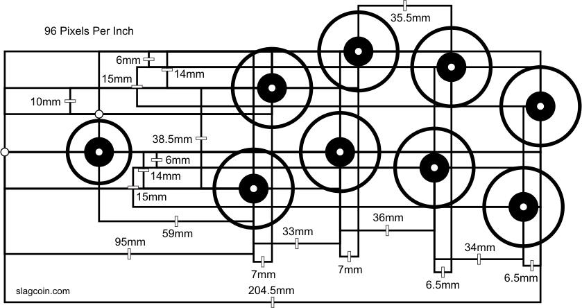
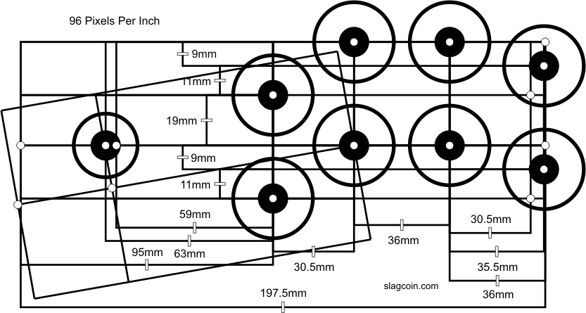
I’ll get some images up soon! Other than the Bill of Materials, priority for the past few days was spent on making a mockup of the player 1 button panel in SolidWorks, referenced from slagcoin‘s excellent “Panel Layout” page. Coupled with my current EDSGN 496A course in this powerful 3D CAD application, creating a virtualization of the controller’s entire housing will help me avoid costly mistakes once construction begins. For now, I plan to use the P1 (and possibly P2) Sega-type layouts for this panel due to their ergonomic, if unorthodox, slanting. You can see the 2D CAD diagrams in the eighth and ninth images down that page, or just click here and here for the 96dpi images.
Earlier today, I spent a few minutes revisiting the now-well-worn Pop’n Music Arcade-Style Controller in order to measure all of its panel thicknesses. My plan is to reference these thicknesses for this project, especially since Sanwa’s famous OBSN-30 screw-in arcade buttons can only take surfaces up to ~1/4″ thick, while the analog joysticks and spinners can mount on heavier stock. On a side note, it’s a shame I didn’t keep strict documentation of the materials – and more importantly, the dimensions – used in building the ASC, though, in case I ever plan to construct another one some day.
Pop’n Music Arcade-Style Controller panel thicknesses:
- Top, sides, and bottom sliding cover handle: 5/8″ pine plywood
- Bottom sliding cover: 1/2″ pine plywood
- Top button reinforcement underlay: 7/32″ birch plywood
- Top overlay: 3/32″ clear polycarbonate
October 1, 2010
Taking advantage of opportunities may require rescheduling others, right? My mom and dad came to visit today in light of Penn State’s “Parents & Families Weekend”, and to reduce future trips to the Home Depot and Lowe’s off campus, we spent a couple hours to acquire the largest items on the (still-in-progress) Bill of Materials. Believe me when I say that medium density fiberboard is very heavy stuff!
- 2 2’x4′ sheets of 3/4″-thick medium-density fiberboard
- 1 2’x4′ sheet of 1/2″-thick medium-density fiberboard
- 1 2’x4′ sheet of 1/4″-thick medium-density fiberboard
- 1 sheet of 3/32″-thick clear polycarbonate
- 1 14″ full-extension drawer slide set (for the keyboard drawer)
- 1 black barrel-style door bolt set (for locking the top playing surface)
- 2 black t-hinges
- 2 heavy-duty black drawer pulls (for carrying handles)
- 6 corner braces
October 4, 2010
How about a progress screenshot in SolidWorks this early Monday morning?

October 5, 2010
More work on the enclosure design. I had to rearrange the locations of the spinner holes to decrease the overall width of the controller. It turns out the typical modern pinball machine is about 29″ wide, so if I went with the previous controller layout above, it would’ve been a foot over! I think ~34.5″ between the left and right panels is more manageable, if still slightly uncomfortable for most players; however, anything less than that would’ve required me to rearrange a lot of buttons in undesirable ways.
Earlier yesterday, I went back to the Visual Arts Building and the Stuckeman Family Building (Penn State’s School of Architecture) to discuss with the machine shop technicians in both locations about constructing the controller enclosure. Part of the process will involve using a large 2.5-axis CNC milling machine in Stuckeman for cutting the majority of the pieces. In particular are the Lexan overlay and the two joystick-button panels, whose feature spacings require very tight tolerances that I can’t manage by hand. Besides, I’d rather use the resources available to me to help make this whole project a little easier.
Alas, as I found out from talking with the shop head in Stuckeman, 1/4″-thick MDF does not hold up well at all when cut thin – as in, the <= 5mm distance between the Sanwa player buttons on the two joystick-button panels. It became very obvious when a sample piece he cut broke like a toothpick in my hands! I was strongly suggested to use phenolic plastic (Grade XX Garolite, specifically) instead, and after toying with the idea, I'll be ordering some in the coming days.

October 7, 2010
Another model update today. The end of the design phase is nigh…
I’ve made a tentative decision to switch from Sanwa’s 30mm pushbuttons to Seimitsu’s 30mm versions, mainly due to the latter’s 9mm maximum mounting depth versus the former’s ~6.35mm. This will avoid having to flush-mount the buttons under the Lexan overlay and milling 35mm circles with excessively-close spacings. The per-unit cost is the same as Sanwa’s, and there’s one more bonus: a truly-authentic button height!

October 8, 2010
Went downtown to the Music Underground store (formerly City Lights Records) yesterday between classes to obtain a few button location/spacing measurements on their arcade’s Gottlieb and Stern pinball machines. And with that, there should remain only minor adjustments to the SolidWorks model from here on out. Final measurements will be implemented once all control components, such as pushbuttons and joysticks, arrive.
Below is what the model looks like now. I need to add bolt holes for the carrying handles, plus the Lexan overlay panels where distances between the panels’ edges and any bezels are fairly large – i.e., more than 4 inches or so – to help keep them pinned down. I’ve added an additional layer of sketches on each of the overlays for the purpose of exporting high-resolution guide drawings in light of possible future artwork. Note that the red circles that appear larger than their corresponding mounting holes were done on purpose: they’re the maximum outer diameters for the pushbutton bezels, joystick dust cover washers, spinner knobs, trackball trim flange, and keyboard drawer pull.

October 11, 2010
Enough with being obsessive-compulsive…I think I’m done with the SolidWorks stuff for now.
Any future model updates will need to be performed after I finish the Bill of Materials in a couple days, order everything, and receive the parts. Areas like the illuminated P1/P2 coin and start button holes were adjusted at the last moment yesterday since I forgot they required 0.97″-diameter holes as opposed to 1.125″. And thanks to Joe Sherman’s suggestion, I’ve added intake vents on the right panel for better ventilation.
In addition to changing out the Sanwa player buttons for Seimitsu versions, I’ve made the decision to switch the SlikStik Tornado Spinners with TurboTwist 2 versions, since the latter are much easier to mount (a standard 1.125″-diameter hole is all that’s needed) and cost slightly less.

October 13, 2010
If I said that construction started today, would that be out of schedule? How about if I employed a 50,000-psi abrasive water jet to create one part far faster than I could’ve by hand? Oh, this was fun.
Thanks to Gavin at the Penn State Learning Factory for running their OMAX 2626 JetMachining Center so I could cut out the 1/16″-thick aluminum rear connection plate. This piece had to be made with higher precision than most of the other components; so given my afternoon schedule was open and that all the parts to be mounted on the plate were already confirmed and/or ordered, I gave it a go. A quick and easy job overall, especially since SolidWorks can directly export 1:1-scaled DXF files.
You may have noticed a slight deviation of the plate’s edges from true horizontal and vertical in the last photo – and you’d be right. Due to assignment of the 5-degree tilted top panel with the origin and front/top/right planes in SolidWorks, all of the non-tilted pieces (that is, the ones parallel and normal to the table the controller will rest on) were thrown out of alignment by five degrees as well in the projection views. That’s because I designed the top panel first, then made everything else relative to it while remaining in assembly mode. Whoops, that’s my first obvious design mistake. The lesson: create the parts separately, then align and adjust them to each other as needed. Don’t design all of them in one assembly relative to one coordinate system unless necessary – which in this case, wasn’t, except for the bottom panel’s sketch extrude converted from the top’s.
Regardless, the abrasive water jet still cut the plate square, but since the alignment issue potentially wastes more raw material, it’s something to be aware of next time.


 - 10-13-10")
Received my first mailed package today for this project: a couple of Qualtek 762-18/003 snap-in IEC fused power input modules. Nothing particularly special, except I got a nice deal for the two off eBay! I only need one of these for the project, but perhaps the future will dictate otherwise.
They fit well into the machined aluminum panel from yesterday, but I may buff down the latter so the shiny surface really shows off – not that anyone would look behind the controller, right?

October 18, 2010
Got my two spinners ordered! Not the ones for my nonexistent car, of course, but these compact USB units from GroovyGameGear.com. I also snapped up two heavier knobs, some LED-lit pushbuttons, and a few 12-position terminal blocks for ease of wiring below the control panel.
As you could infer by now, the Bill of Materials is basically solidified. Now the ordering and waiting shall continue…
October 20, 2010
More stuff will be coming in the following days, including lots of pushbuttons, connectors, and interface boards. I should plan one last trip to the Home Depot soon to acquire the remaining hardware…
October 23, 2010
It’s like Christmas when a small box opens up to reveal a stash of small, but awesome, items. Like pushbuttons and USB panel connectors! The guys at Lizard Lick Amusements are very fast at their job, so thanks to them I get to click ’em sooner. I also received the 7-port USB hub, cold cathode lamps, and fan guard, as seen here:

I took one last trip with Joe to the Home Depot to pick up some primer/paint, brushes, enclosure locks and miscellaneous hardware, and a couple more panels of 3/4″-thick MDF – the latter for “just in case” moments. I’m almost done with the ordering process…
On the negative end, though, I found out that the machined rear aluminum connection cover that the USB panel connectors will mount to was improperly dimensioned: the pass-through holes were ever-so-slightly too small, resulting in an overly-snug fit. Oh well…I’ll have to file them manually when the time comes, and update the SolidWorks design for post-construction reference.
October 25, 2010
Got my spinners, knobs, LED driver board, and the remaining pushbuttons today from the GroovyGameGear.com store. All that remains are the joysticks, trackball, power supply parts, the I-Pac keyboard encoder board, and a few extra interface accessories.
November 3, 2010
So this is what happens when midterms land on top of this project: no updates until they’re done! I finally received my last component today and will move everything to the Visual Arts Building tonight for easier access to the building’s machine shop (and the Stuckeman Family Building’s shop next door). Construction will continue either this week or next week.
November 8, 2010
All right! Finally went back to building this controller today, beginning with a lot of milling action at the Stuckeman Family Building’s model shop. Thanks to Jamie Heilman, the architecture department’s digital fabrication supervisor, I got a chance to learn VisualMill and use the facility’s Precix 2.5-dimension table to cut out the MDF parts. It astonished me how accurate, precise, and repeatable this machine is: all of the parts fit like a glove with one another once they were done, with no adjustment sanding necessary. Nevertheless, medium-density fiberboard kicks up a LOT of debris when cut, because it’s essentially compressed sawdust to begin with. I wonder how many years it subtracted from my life?
I’ll be returning to Stuckeman tomorrow to make the Garolite and Lexan parts. This is getting exciting…


Finished up cutting the Lexan and Garolite parts today, which signals the end of my CAM sessions. Garolite, being a phenolic-based material, does NOT smell pleasant when machined; thankfully, there were only four pieces! Since I didn’t have shop training in time for this project, Allen Sutley, the Stuckeman model shop supervisor, mitered the front, rear, and side panels of the enclosure so they’d all fit into the bottom panel’s recesses. He also re-made the keyboard drawer’s side and rear panels out of some plywood since the 1/2″-thick MDF wasn’t holding up after yesterday’s cuts. Thank you for helping to speed this project along.


Here’s a “table-level” 720p video of my Lexan pieces being cut out on the Precix milling machine. Note that the Nikon D90 I’m borrowing for this project’s documentation can shoot decent video in addition to the photos posted thus far. Watch those plastic shavings fly!
If you’re wondering, Mr. Sutley on the left wasn’t keeling over in pain 7 seconds in. That’s just his personality.
November 10, 2010
Routed out the trackball recess underneath the top panel this evening. Thanks again for the help, Mr. Sutley.
The next step is to drill out the holes for the trackball’s blind mounting inserts, then cut the 1/16″-wide slot around the periphery of the top and bottom panels for the T-molding. Can’t wait to get this enclosure painted and assembled!
November 11, 2010
Got the T-molding channels routed out with a 1/16″-wide slot cutter bit and drilled out the trackball holes at the Visual Arts Building’s shop. No images today, though, since I need to borrow a D90 again.
November 17, 2010
Scratch out my excitement back on November 10: I think I’ve developed a distaste for painting. Not artistic painting, mind you, but “utilitarian” painting a là this. After making a nasty series of mistakes (read: in haste) on most of the MDF panels using overly-thick brush-on primer, I had to sand everything off and head to the Home Depot yet again. I bought about a dozen cans of Rust-Oleum spray primer and semi-gloss black paint, then spent another night in front of the spray booth up in the studio slowly re-covering everything twice. Definitely a lesson on what patience allows for that rushing doesn’t…

November 20, 2010
Back home for Thanksgiving break with this project in tow. I installed the Lexan overlay sheets and the front brackets over the past two days, then upon returning last night, got all the input devices, cam locks, and T-molding in as well. Although artwork still needs to be designed, I’m leaving in the controls for wiring and testing purposes until it’s time for printing. Once I get back to Penn State, I’ll also cut the rest of the aluminum brackets so the top panel can lock onto the rest of the enclosure.

November 21, 2010
Power supply section is done! The 13.6VDC 5A switching unit and dual-output 3A DC-DC converter were installed tonight, along with the seven-port D-Link USB hub and appropriate connecting hardware; a second identical hub will be added soon so I can attach all eight USB devices (including the two rear ports). The DC-DC converter uses two LM2596 bucking ICs with outputs governed by selectable resistor combinations. I set one output to 5V for the hub and the second to 3.3V for running the cooling fan at low speed; the latter can be changed to accommodate for heat buildup. 13.6V directly from the switching supply will drive the intelligent LED illumination system.

Here’s the whole controller to date. Actually, it’s pretty much what the finished product will look like without the artwork. This is one heavy unit with all that MDF! I reckon it’s about 50-60lb., stretching the “Portable” term a little thin, don’t you think?

November 26, 2010
Since the previous update, I’ve spent a few late nights wiring this controller up before I head back to Penn State. It was a straightforward yet tedious process: mount the I-PAC/LED-Wiz/other USB controllers with insulated standoffs, connect the trackball, connect Player 1’s and Player 2’s dedicated controls to the I-PAC, connect the MAME control buttons, then the pinball controls located on the front and side panels, the lighting circuits to the LED-Wiz, and finally the cold cathode lamp for logo illumination. I used a lot of color-coded 20AWG wire, screw-on nylon cable clamps, crimp connectors, and zip ties in the process to keep things neat and separated (especially since I’ll be removing the buttons later to mount artwork). The USB cables were added last once everything was functionally verified. Mapping of the buttons’ and joysticks’ functions were performed with Ultimarc’s WinIPAC and UltraMap utilities, respectively.
Not all was without problems, though. Thanks to my sister during a testing session, we discovered that two of the Player 2 buttons were “ghost triggering” the Player 1 Start and Coin buttons. After probing with a multimeter and a silicon rectifier diode placed at various points in the Player 2 signal lines, I found that a ground voltage difference between the Player 2 UltraStik 360‘s USB ground and the I-PAC’s common ground was large enough to cause (non-damaging) reverse current flow into the I-PAC. In addition, the LED indicators for Num/Caps/Scroll lock glowed faintly during ghosting, giving me some clues. Resolving the issue was somewhat strange: I took the positive line off the I-PAC’s keyboard status header, then soldered the silicon rectifier diode between the LED-Wiz’s +5V line and the aforementioned LED indicators – which are still grounded through the I-PAC! It stopped the unintended inputs, but hasn’t prevented the indicators from lighting when the two Player 2 buttons were pressed. Oh well.
With that, here is the controller to date. I’ve tested older MAME ROMs like Pulstar and early Gradius installations, as well as Windows/DOS titles such as Super Mario Bros. X, with success so far. Newer games a là Street Fighter IV and Super Meat Boy will need to wait for a higher-powered PC back at school. I also ran the LED-Wiz controller through its paces using GroovyGameGear’s LumAura Engine and LuminAudio light organ applications, so these are shots with the button illumination enabled. I should definitely give that trackball an RGB LED some day…


And a bonus photo: firing up Tyrian 2000, a top-down shoot-em-up almost lost in my memory until Joe revived it just a few months ago.

To-dos: make the remaining aluminum brackets, design and print artwork, test (and play!) more single- and multi-player games, write the final report, and create the final presentation. Almost there…
December 1, 2010
Well, as of today, I can safely say that the controller, minus the artwork, is finished. After three additional shop sessions – two of them this evening – I machined out the rest of the aluminum brackets, mounted them, and after some last-minute adjustments to the front brackets, got everything fully mated with one another for the first time. Joe and I performed a final controls test and then muscled the heavy controller into his car…for gaming night with the Penn State Anime Organization!
Aside from a few one-on-one testing sessions in the Visual Arts Building’s graduate studio, this was the first open demo of the controller. Here’s a summary of the games we “broke in” tonight:
Super Mario Bros. X: the same game I played over Thanksgiving, now in a crowd setting. Reception was positive, especially since the game was designed for an 8-way directional pad and four digital buttons, which the control panel emulated easily. Co-op and Battle modes were especially entertaining to watch as my friends relived days of the SNES’ blockbuster Super Mario World series.
Melty Blood: Act Cadenza ver.B: the standout title of the night on the control panel, this Japanese anime-style fighting game is a Windows port of the arcade version of similar name. I chose this title to verify that the panel can be used natively on another computer without requiring separate driver installations (thanks for lending us your laptop, Chelsie Ehasz!). While I mistakenly mapped the A, B, and C buttons to the lower row of the players’ controls, where D and A+B+C “Heat” should be, the overall reception was fantastic. There was a fairly constant crowd hanging around through the hour, and even for those who weren’t proficient at fighters, the “button-mashing” fest that is Melty Blood didn’t harm the controller one bit while allowing enjoyment for all.
OpenTyrian: an SDL port of the game I tested over Thanksgiving break, with some great graphical enhancements. This was the last game of the night, and more of an experiment to see whether a 2-player keyboard and mouse-based game can run on the control panel. While there were issues with the AutoHotkey-based mouse emulation script for the analog joysticks and some minor calibration errors (possibly due to the sticks not centering perfectly), we still had a good time shooting up hundreds of enemies in the minutes before closing up.
After each game, I asked those who played to provide some feedback using a survey I wrote up earlier. While the praises were much appreciated, I also looked over what could (or should) be done to the panel in the future: most advice was directed towards adding button labels, fixing the calibration errors in OpenTyrian, and lowering the excessive mass of the controller. For your interests, here’s a copy of the survey I handed out, followed by some photos of the tests:
MAME Control Panel Survey – December 1, 2010 (PDF)


December 3, 2010
Here’s some top panel art in progress! It looks like SolidWorks and GIMP will be getting use for a couple more days. Thanks to Jason Bolt and Grace Turner for creating and rendering the gorgeous fractal with Apophysis. The original size of the PNG below is a whopping 8000×4000 pixels! Hopefully that explains the 200dpi print on deck…

December 4, 2010
Top panel artwork is printed and mounted! After two scratched prints yesterday due to incorrect paper settings and a lack of proper maintenance, a fellow photography grad student and I finagled the studio’s 48″ plotter to output an undamaged copy. But as life would have it, this was only the beginning of another lesson on patience: trimming out the numerous features with an X-ACTO knife, without making a serious mistake nor injuring myself, took nearly four hours. I touched up the cut edges with black India ink so that off-angle viewing would not reveal any white against the black panel. Then I removed all the top panel’s quick-connects, pushbuttons and other controls, cam locks, and the Lexan overlay. I carefully wiped down the top panel and the Lexan surface, put in the artwork, slowly reinstalled everything, and finally verified that the controller worked like before. Thankfully, it did.
Other than the final report and presentation, all that’s left is to create the illuminated logo, then print and install it. Due to shortage of time, I’ll forgo generating front and side panel art until the official business is over.


December 5, 2010 (part 1)
Think you can figure out the inspiration for the illuminated logo?
The answer is a standout memory of my childhood. And because the controller is, well, massive.
December 5, 2010 (part 2)
This is it. After 3 months of design and construction, the portable MAME control panel is finally done. Here’s what happened today:
Earlier, I printed out the illuminated logo on matte card stock, made some last-minute width adjustments to its mounting tabs, trimmed it with an X-ACTO blade, touched India ink on the raw edges, and then inserted it into the top panel. I found that a single cold cathode lamp wasn’t sufficient to display the logo under the strong ambient lighting, so I plugged in another tube (the ballast can handle one or two lamps). I then cut a diffuse reflector from extra card stock, and with some double-sided tape, mounted it around the CCFLs. With the two extra parts in place, the logo now shows off quite well. Note that I’ve decided to leave off artwork on the front and side panels, since the fadeout border on the top panel’s fractal complements well with the solid black on the rest of the controller.


Since a graduated friend of ours from the School of Visual Arts visited this weekend, we spent a few more hours playing Super Mario Bros. X, Melty Blood: Act Cadenza ver.B, Pulstar, Gradius III, and other games. A couple more completed surveys later, and the panel’s ready for the final report.


To close the day, here are three shots under normal, dim, and no light. Those LEDs are so intense…
")
")
")
Special thanks to:
- The Lord, for giving me lessons on patience and persistence, and providing invaluable skills in engineering and art so that I may serve Him and live my life for His glory.
- My parents and sister, for encouragement, support, prayers, and late dinners while I stayed up working into the morning hours.
- Dr. Kyusun Choi, for being a steadfast project mentor and computer engineering professor, a source of encouragement, and a devoted brother in Christ.
- Professor Timothy Wheeler, my EE 403W senior design professor and a great help in keeping this project moving forward throughout the semester.
- Professor Randall Bock of EDSGN 496A – SolidWorks Fundamentals, who taught me how to turn an imagination into a dimensionally-accurate design.
- Allen Sutley and Jamie Heilman of the Department of Architecture‘s Model Shop, who taught me how to turn a dimensionally-accurate design into a CAM-based reality.
- Jerry Bierly and his assistants of the Visual Arts Building’s machine shop, who helped me find suitable mounting hardware and refreshed my equipment training.
- Matt Kenyon of the SoVA’s New Media program, for providing me invaluable working space in the graduate studio and for encouragement throughout.
- Gavin and the rest of the staff at The Learning Factory, for running their abrasive water jet and giving me material selection advice.
- Joe Sherman, who provided rides and a passionate hand in moving materials, the completed controller, and my mind while topping off my common sense and sanity.
- Jason Bolt and Grace Turner, the fractal artists, game designers, testers, and friends who lent their time when opportunities arose.
- Sarah Nesbitt, Vinh Duong, Nate Kling, Kurt Kling, Kyle Hood, Dan Cicconi, and the rest of the studio members who overcame printing problems, beta-tested the controller, supported my official presentation, and kept all of us in high spirits into the night.
- Ryan Friel and his insatiable passion for video games, particularly fighters, for advice and for demonstrating his high-end controller so I could understand proper button layouts.
- The gamers of the Penn State Anime Organization, thorough evaluators of the control panel during its first public demo.
- slagcoin.com, for the ergonomic Sega joystick and button layouts, plus sound advice on fightstick construction.
- The Build Your Own Arcade Controls FAQ, BYOAC forum, and BYOAC wiki, which got me interested in the DIY arcade community.
- ArcadeCab.com, providers of free MAME cabinet plans. Although I couldn’t build a full-size stand-up unit, the site sparked the critical beginnings of this project.
- Jeff’s ULTIMATE MAME Cabinet Project, whose bold development inspired me to go further with my own design.
- Andy at Ultimarc.com, the employees of Lizard Lick Amusements and GroovyGameGear.com, and the rest of my component providers for outstanding service and fast shipping.
- The developers of MAME, who created this software to relive the golden days of video arcades.
- And last – but not least – you, for showing your genuine interest and sharing the belief that video games are cool.
~ You got a high score! ~
